
Capacitors are electronic components that store electrical charge and energy. They are commonly used in circuits to filter signals, block direct current, and stabilize voltage.
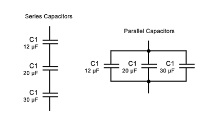
When capacitors are connected in series, their total capacitance decreases, and their total voltage rating increases. This is because the charge on each capacitor is the same, and the voltage across each capacitor is proportional to its capacitance. Therefore, the voltage across each capacitor in a series connection is divided according to the ratio of its capacitance to the total capacitance. The total capacitance of capacitors in series can be calculated using the formula:
1/C_total = 1/C1 + 1/C2 + … + 1/Cn
where C1, C2, …, Cn are the capacitances of individual capacitors.
When capacitors are connected in parallel, their total capacitance increases, and their total voltage rating remains the same. This is because the voltage across each capacitor in a parallel connection is the same, and the charge on each capacitor is proportional to its capacitance. Therefore, the total charge stored in a parallel combination of capacitors is the sum of the charges stored in each individual capacitor. The total capacitance of capacitors in parallel can be calculated using the formula:
C_total = C1 + C2 + … + Cn
where C1, C2, …, Cn are the capacitances of individual capacitors.
What is Required Capacitors in Series and Parallel
The capacitance required in a circuit depends on the specific application and the electrical properties of the other components in the circuit. In some cases, a single capacitor may be sufficient, while in other cases, multiple capacitors may need to be connected in series or parallel to achieve the desired capacitance.
When connecting capacitors in series, the total capacitance of the combination will be less than the capacitance of any individual capacitor. Therefore, if a specific capacitance value is required in a circuit and only capacitors with lower capacitance values are available, they can be connected in series to achieve the desired value. For example, if a circuit requires a 10μF capacitor, and only 5μF capacitors are available, two 5μF capacitors can be connected in series to obtain a total capacitance of 10μF.
When connecting capacitors in parallel, the total capacitance of the combination will be greater than the capacitance of any individual capacitor. Therefore, if a specific capacitance value is required in a circuit and only capacitors with higher capacitance values are available, they can be connected in parallel to achieve the desired value. For example, if a circuit requires a 10μF capacitor, and only 20μF capacitors are available, two 20μF capacitors can be connected in parallel to obtain a total capacitance of 40μF, which can be then divided into two equal halves by connecting the two combinations in series.
It is important to note that when connecting capacitors in series or parallel, their voltage ratings must be taken into consideration to prevent damaging the capacitors or other components in the circuit.
When is Required Capacitors in Series and Parallel
Capacitors are often connected in series or parallel to achieve specific capacitance values and to meet the requirements of a particular circuit.
Capacitors in series are typically used when the required capacitance value is not available in a single capacitor or when a high voltage rating is needed. Connecting capacitors in series reduces the overall capacitance of the circuit but increases the voltage rating of the circuit. This is because the voltage across each capacitor in a series connection is divided based on the ratio of its capacitance to the total capacitance. Therefore, the voltage rating of the series connection is the sum of the voltage ratings of each individual capacitor. Capacitors in series are commonly used in high voltage applications such as power supplies, motor controllers, and audio amplifiers.
Capacitors in parallel are typically used when a larger capacitance value is required than what is available in a single capacitor or when a lower equivalent series resistance (ESR) is needed. Connecting capacitors in parallel increases the overall capacitance of the circuit while maintaining the same voltage rating. This is because the charge stored in each capacitor in a parallel connection adds up to the total charge stored in the circuit. Therefore, the total capacitance of the parallel connection is the sum of the capacitance of each individual capacitor. Capacitors in parallel are commonly used in low-frequency applications such as audio circuits, decoupling capacitors in power supplies, and filter circuits.
It is important to note that the capacitance and voltage ratings of capacitors must be chosen appropriately when connecting capacitors in series or parallel to prevent damage to the capacitors or other components in the circuit. The choice of the capacitor configuration depends on the specific requirements of the circuit and the availability of suitable capacitors.
Where is Required Capacitors in Series and Parallel
Capacitors in series or parallel can be required in a variety of electronic applications. Here are some examples:
- Power supplies: In power supplies, capacitors are used to smooth out voltage ripples and provide stable DC voltage to the load. Large capacitors with high voltage ratings are often connected in series to achieve the required voltage rating.
- Audio circuits: In audio circuits, capacitors are used to block DC voltage and allow only AC signals to pass through. Capacitors with low ESR and high capacitance are connected in parallel to reduce noise and improve signal quality.
- Motor controllers: Capacitors are used in motor controllers to smooth out the voltage and provide a stable DC voltage to the motor. High-voltage capacitors connected in series may be used to achieve the required voltage rating.
- Filter circuits: Capacitors are used in filter circuits to pass specific frequency ranges and block others. Capacitors with different capacitance values may be connected in series or parallel to achieve the desired frequency response.
- Decoupling capacitors: In decoupling capacitors, capacitors are used to filter out high-frequency noise and provide a low-impedance path for high-frequency current. Capacitors with low ESR and high capacitance are often connected in parallel to provide effective decoupling.
The choice of the capacitor configuration depends on the specific requirements of the circuit and the availability of suitable capacitors. It is important to consider the capacitance and voltage ratings of the capacitors and their placement in the circuit to ensure reliable and efficient operation.
How is Required Capacitors in Series and Parallel
To calculate the total capacitance of capacitors connected in series, the following formula is used:
1/C_total = 1/C1 + 1/C2 + … + 1/Cn
where C_total is the total capacitance, C1, C2, …, Cn are the individual capacitances of the capacitors connected in series.
For example, if two capacitors with capacitances of 2μF and 4μF are connected in series, the total capacitance of the combination can be calculated as:
1/C_total = 1/2μF + 1/4μF 1/C_total = 0.5 + 0.25 1/C_total = 0.75 C_total = 1.33μF
To calculate the total capacitance of capacitors connected in parallel, the following formula is used:
C_total = C1 + C2 + … + Cn
where C_total is the total capacitance, C1, C2, …, Cn are the individual capacitances of the capacitors connected in parallel.
For example, if two capacitors with capacitances of 10μF and 20μF are connected in parallel, the total capacitance of the combination can be calculated as:
C_total = 10μF + 20μF C_total = 30μF
It is important to note that when capacitors are connected in series, their voltage ratings add up, and the capacitor with the lowest voltage rating will determine the maximum voltage that can be applied to the series combination. When capacitors are connected in parallel, their voltage ratings should be the same or higher than the maximum voltage applied to the parallel combination. Additionally, it is important to choose capacitors with similar tolerances to ensure that the total capacitance value remains within the desired range.
Production of Capacitors in Series and Parallel
Capacitors can be produced in series or parallel configurations by connecting individual capacitors together in the desired configuration. This can be done manually by soldering or using clamps to connect the leads of individual capacitors, or it can be done using specialized equipment in a manufacturing setting.
In a manufacturing setting, the process of producing capacitors in series or parallel is generally automated and involves the use of machinery such as pick-and-place machines, reflow ovens, and testing equipment. The process typically involves the following steps:
- Selection of individual capacitors with the desired capacitance and voltage rating.
- Connection of the capacitors in series or parallel using specialized machinery such as a pick-and-place machine or a reflow oven.
- Testing of the capacitance and voltage rating of the series or parallel combination using specialized equipment such as a capacitance meter or a high-voltage tester.
- Packaging of the capacitors in series or parallel for shipment to customers.
The manufacturing process for capacitors in series or parallel can vary depending on the type of capacitor and the specific application. For example, electrolytic capacitors, ceramic capacitors, and film capacitors may have different manufacturing processes and requirements for producing them in series or parallel.
Overall, the production of capacitors in series or parallel involves careful selection and connection of individual capacitors, as well as thorough testing to ensure that the desired capacitance and voltage rating are achieved.
Case Study on Capacitors in Series and Parallel
One example of the use of capacitors in series and parallel is in power supply applications, where capacitors are often connected in parallel to provide a smoother and more stable output voltage.
In a typical power supply circuit, an AC voltage is converted to a DC voltage using a rectifier circuit. However, the output of the rectifier circuit contains voltage ripples, which can cause unwanted noise and instability in the circuit. To smooth out the voltage ripples, capacitors are often connected in parallel to the output of the rectifier circuit.
In this case study, we will consider the design of a power supply circuit using capacitors in series and parallel.
Suppose we need to design a power supply that provides a regulated DC voltage of 12V with a maximum current output of 1A. We will use a bridge rectifier circuit to convert the AC voltage to a DC voltage, and we will use capacitors in series and parallel to smooth out the voltage ripples.
First, we need to calculate the required capacitance of the capacitors. To do this, we can use the formula:
C = I x T / V
where C is the capacitance, I is the maximum current output, T is the time period of the voltage ripple (which is typically the inverse of the frequency of the AC voltage), and V is the voltage ripple.
For example, if we assume a voltage ripple of 0.1V and a frequency of 60Hz, the time period of the voltage ripple would be 1/60 = 0.0167s. If we also assume a maximum current output of 1A, the required capacitance can be calculated as:
C = 1A x 0.0167s / 0.1V = 0.167F
Next, we need to select capacitors with the appropriate voltage rating and tolerance to achieve the desired capacitance. Suppose we decide to use four capacitors in parallel, each with a capacitance of 0.047F and a voltage rating of 25V. To achieve the desired capacitance of 0.167F, we can connect the four capacitors in parallel, giving a total capacitance of 0.188F. The voltage rating of the parallel combination is 25V.
Finally, to achieve the required output voltage of 12V, we can connect three sets of capacitors in series. Each set consists of two capacitors connected in parallel, giving a total capacitance of 0.376F and a voltage rating of 50V. The three sets of capacitors are connected in series, giving a total capacitance of 0.125F and a voltage rating of 150V.
The complete power supply circuit can be built using these capacitors, along with a regulator circuit to maintain a stable output voltage. The capacitors in parallel will help to smooth out the voltage ripples, while the capacitors in series will provide the required voltage rating.
Overall, this case study illustrates how capacitors can be connected in series and parallel to achieve the desired capacitance and voltage rating for a power supply circuit. Careful selection and calculation of the capacitance and voltage rating is essential to ensure reliable and efficient operation of the circuit.
White paper on Capacitors in Series and Parallel
Introduction
Capacitors are electronic components that store electric charge and energy. They are used in a wide range of electronic circuits, including power supplies, filters, timing circuits, and oscillators. In some applications, it may be necessary to connect capacitors in series or parallel to achieve the desired capacitance, voltage rating, or other characteristics. This white paper provides an overview of capacitors in series and parallel, including their advantages, disadvantages, and applications.
Capacitors in Series
When capacitors are connected in series, their effective capacitance is reduced. The formula for calculating the effective capacitance of capacitors in series is:
Ceq = 1 / (1/C1 + 1/C2 + … + 1/Cn)
where Ceq is the effective capacitance, C1, C2, and Cn are the capacitances of the individual capacitors.
For example, if two capacitors with capacitances of 10μF and 20μF are connected in series, their effective capacitance can be calculated as:
Ceq = 1 / (1/10μF + 1/20μF) = 6.7μF
One advantage of connecting capacitors in series is that it can increase the voltage rating of the circuit. The voltage rating of the series combination is equal to the sum of the voltage ratings of the individual capacitors.
However, a disadvantage of connecting capacitors in series is that it can decrease the overall capacitance of the circuit. This can limit the ability of the circuit to store charge and energy, and can affect the frequency response of the circuit.
Capacitors in Parallel
When capacitors are connected in parallel, their effective capacitance is increased. The formula for calculating the effective capacitance of capacitors in parallel is:
Ceq = C1 + C2 + … + Cn
where Ceq is the effective capacitance, C1, C2, and Cn are the capacitances of the individual capacitors.
For example, if two capacitors with capacitances of 10μF and 20μF are connected in parallel, their effective capacitance can be calculated as:
Ceq = 10μF + 20μF = 30μF
One advantage of connecting capacitors in parallel is that it can increase the overall capacitance of the circuit. This can improve the ability of the circuit to store charge and energy, and can affect the frequency response of the circuit.
However, a disadvantage of connecting capacitors in parallel is that it can decrease the voltage rating of the circuit. The voltage rating of the parallel combination is equal to the voltage rating of the individual capacitors.
Applications
Capacitors in series and parallel are used in a variety of electronic circuits. Some common applications include:
Power supplies: Capacitors are often connected in parallel to the output of a rectifier circuit in a power supply. This helps to smooth out the voltage ripples and provide a stable DC voltage.
Filters: Capacitors are used in filters to block or pass certain frequencies. Capacitors in series or parallel can be used to achieve the desired frequency response.
Timing circuits: Capacitors are used in timing circuits to control the rate of charging and discharging. Capacitors in series or parallel can be used to achieve the desired timing characteristics.
Oscillators: Capacitors are used in oscillators to control the frequency of the output signal. Capacitors in series or parallel can be used to achieve the desired frequency response.
Conclusion
Connecting capacitors in series or parallel can have a significant impact on the overall characteristics of an electronic circuit. By calculating the effective capacitance and voltage rating of the combination, designers can achieve the desired performance and functionality. Capacitors in series can increase the voltage rating but decrease the overall capacitance, while capacitors in parallel can increase the overall capacitance but decrease the voltage rating. Capacitors in series and parallel are used in a variety of applications, including power supplies, filters, timing circuits, and oscillators. Careful selection and calculation of capacitors in series or parallel is critical to ensuring the performance and reliability of electronic circuits.