
RC, LR, LC, and LCR are different types of electrical circuits that consist of resistors (R), capacitors (C), and inductors (L).
RC Circuit: An RC circuit is a circuit that consists of a resistor and a capacitor connected in series or parallel. In a series RC circuit, the resistor and capacitor are connected in series, and in a parallel RC circuit, the resistor and capacitor are connected in parallel. RC circuits are commonly used in electronic filters, time delay circuits, and frequency response analysis.
LR Circuit: An LR circuit is a circuit that consists of a resistor and an inductor connected in series or parallel. In a series LR circuit, the resistor and inductor are connected in series, and in a parallel LR circuit, the resistor and inductor are connected in parallel. LR circuits are commonly used in electronic filters, inductance measurement, and frequency response analysis.
LC Circuit: An LC circuit is a circuit that consists of a capacitor and an inductor connected in series or parallel. In a series LC circuit, the capacitor and inductor are connected in series, and in a parallel LC circuit, the capacitor and inductor are connected in parallel. LC circuits are commonly used in oscillators, filters, and resonant circuits.
LCR Circuit: An LCR circuit is a circuit that consists of a resistor, a capacitor, and an inductor connected in series. LCR circuits are commonly used in electronic filters, oscillators, and resonance circuits. LCR circuits are also known as resonant circuits, and they exhibit resonance at a specific frequency, which is determined by the values of the resistor, capacitor, and inductor in the circuit.
What is Required RC, LR, LC and LCR(in series) circuits
To calculate the values required for an RC, LR, LC, or LCR circuit in series, you would need to know the specific characteristics of the circuit that you want to design.
For an RC circuit, you would need to know the resistance value of the resistor (R) and the capacitance value of the capacitor (C) that are required to achieve the desired frequency response or time constant of the circuit. You can use the following formula to calculate the time constant (τ) of an RC circuit:
τ = R * C
For an LR circuit, you would need to know the resistance value of the resistor (R) and the inductance value of the inductor (L) that are required to achieve the desired frequency response or time constant of the circuit. You can use the following formula to calculate the time constant (τ) of an LR circuit:
τ = L / R
For an LC circuit, you would need to know the capacitance value of the capacitor (C) and the inductance value of the inductor (L) that are required to achieve the desired frequency response or resonant frequency of the circuit. You can use the following formula to calculate the resonant frequency (f) of an LC circuit:
f = 1 / (2 * π * √(L * C))
For an LCR circuit in series, you would need to know the resistance value of the resistor (R), the capacitance value of the capacitor (C), and the inductance value of the inductor (L) that are required to achieve the desired frequency response or resonant frequency of the circuit. You can use the following formula to calculate the resonant frequency (f) of an LCR circuit:
f = 1 / (2 * π * √(L * C))
and the quality factor (Q) of the circuit:
Q = √(L / R * C)
The quality factor is a measure of how underdamped or overdamped the circuit is and can be used to determine the bandwidth of the circuit.
When is Required RC, LR, LC and LCR(in series) circuits
RC, LR, LC, and LCR circuits in series are commonly used in a variety of electronic applications such as filters, oscillators, and resonant circuits.
An RC circuit in series can be used as a low-pass filter or high-pass filter depending on how it is configured. A low-pass RC filter passes low-frequency signals while attenuating high-frequency signals, and a high-pass RC filter passes high-frequency signals while attenuating low-frequency signals. RC circuits are also used as timing circuits in applications such as pulse width modulation (PWM) and time delay circuits.
An LR circuit in series can be used as a low-pass filter, high-pass filter, or band-pass filter depending on how it is configured. LR circuits are also used for inductance measurement and frequency response analysis.
An LC circuit in series is commonly used in oscillator circuits, resonant circuits, and frequency filters. The resonant frequency of an LC circuit can be adjusted by changing the values of the capacitor and inductor, and the circuit can be designed to resonate at a specific frequency.
An LCR circuit in series is commonly used in electronic filters, oscillators, and resonance circuits. LCR circuits exhibit resonance at a specific frequency, and the quality factor of the circuit can be adjusted by changing the values of the resistor, capacitor, and inductor. LCR circuits are also used in frequency response analysis and frequency measurement.
Where is Required RC, LR, LC and LCR(in series) circuits
RC, LR, LC, and LCR circuits in series can be found in a variety of electronic devices and systems, including:
- Audio equipment: RC circuits are used in audio crossovers to separate and filter different frequencies for different speakers. LR circuits are used in inductors for audio frequency applications.
- Power supplies: RC circuits are used in power supply filters to smooth out the output voltage. LC filters are used in switching power supplies to reduce the ripple current and voltage.
- Communications systems: RC circuits are used in filters to remove unwanted signals and noise from communication signals. LC circuits are used in RF filters and oscillators.
- Automotive systems: RC circuits are used in the engine control module (ECM) to filter and smooth out sensor signals. LR circuits are used in ignition systems to reduce noise.
- Medical equipment: RC circuits are used in electrocardiogram (ECG) machines to filter out muscle noise. LC circuits are used in magnetic resonance imaging (MRI) machines for resonance circuits.
These are just a few examples of where RC, LR, LC, and LCR circuits in series can be found. They are used in many different applications across a wide range of industries, including electronics, telecommunications, aerospace, automotive, medical, and more.
How is Required RC, LR, LC and LCR(in series) circuits
To design an RC, LR, LC, or LCR circuit in series, you would typically follow these steps:
- Determine the circuit requirements: Determine the circuit’s desired frequency response, resonant frequency, bandwidth, or time constant. This will help you determine the type of circuit that you need to design and the specific values of the components required.
- Choose the component values: Choose the appropriate values of the resistor, capacitor, and/or inductor to meet the circuit requirements. You can use the formulas mentioned earlier to calculate the values of the components needed.
- Calculate the power rating: Once you have determined the values of the components needed, you should calculate the power rating of the components. The power rating should be high enough to handle the maximum current or voltage that will be passing through the circuit.
- Build and test the circuit: Once you have selected the components, you should build the circuit and test it to ensure that it meets the desired specifications. You may need to adjust the values of the components or the circuit configuration to fine-tune the circuit’s performance.
- Troubleshoot any issues: If the circuit does not meet the desired specifications, you may need to troubleshoot the circuit to identify and fix any issues. This may involve measuring the circuit’s performance using test equipment or simulation software and adjusting the circuit as needed.
It’s worth noting that designing RC, LR, LC, or LCR circuits in series can be complex and requires a good understanding of circuit theory and design principles. If you are new to electronics or are unsure about the design process, it may be helpful to consult with a knowledgeable expert or reference a reliable electronics design guide.
Structures of RC, LR, LC and LCR(in series) circuits
RC Circuit:
An RC circuit is a circuit containing both a resistor (R) and a capacitor (C) that are connected together. In this circuit, the resistor and capacitor are connected in series. The circuit can be represented by the following diagram:
   +----R----+
   |         |
V_in         |
   |         |
   C         |
   |         |
   +---------+
     V_out
where V_in is the input voltage, V_out is the output voltage, R is the resistance, and C is the capacitance.
LR Circuit:
An LR circuit is a circuit containing both a resistor (R) and an inductor (L) that are connected together. In this circuit, the resistor and inductor are connected in series. The circuit can be represented by the following diagram:
   +----R----+
   |         |
V_in         |
   |         |
   L         |
   |         |
   +---------+
     V_out
where V_in is the input voltage, V_out is the output voltage, R is the resistance, and L is the inductance.
LC Circuit:
An LC circuit is a circuit containing both a capacitor (C) and an inductor (L) that are connected together. In this circuit, the capacitor and inductor are connected in parallel. The circuit can be represented by the following diagram:
   +---------+
   |         |
V_in         |
   |         |
   L         C
   |         |
   +---------+
     V_out
where V_in is the input voltage, V_out is the output voltage, C is the capacitance, and L is the inductance.
LCR Circuit (in series):
An LCR circuit is a circuit containing all three passive components: a resistor (R), a capacitor (C), and an inductor (L) that are connected together. In this circuit, the resistor, capacitor, and inductor are connected in series. The circuit can be represented by the following diagram:
   +----R----+
   |         |
   L         |
   |         |
   C         |
   |         |
   +---------+
     V_out
where V_out is the output voltage, R is the resistance, C is the capacitance, and L is the inductance.
Case Study on RC, LR, LC and LCR(in series) circuits
Let’s consider a case study involving the four types of circuits: RC, LR, LC, and LCR in series.
Suppose we have a circuit containing a 100 Ω resistor, a 50 mH inductor, and a 10 μF capacitor connected in series with an AC voltage source of 10 V and 60 Hz frequency. We can analyze the behavior of the circuit using various methods and formulas, including Kirchhoff’s voltage law, Ohm’s law, and the formulas for capacitive and inductive reactance.
RC Circuit: In an RC circuit, the capacitor acts as a frequency-dependent resistor, and its impedance can be calculated using the formula Z_C = 1/(jωC), where j is the imaginary unit, ω is the angular frequency (2πf), and C is the capacitance. At the frequency of 60 Hz, the capacitive reactance (X_C) is X_C = 1/(2πfC) = 265.2 Ω. Thus, the total impedance of the circuit (Z_total) can be calculated using the formula Z_total = R + Z_C = 365.2 Ω. The current flowing through the circuit can be calculated using Ohm’s law, which gives I = V/R = 0.1 A. The voltage drop across the resistor is IR = 10 V, and the voltage drop across the capacitor is IZ_C = -2.65 V (the negative sign indicates that the voltage drop is 180 degrees out of phase with the current). The voltage across the capacitor leads the current by 90 degrees.
LR Circuit: In an LR circuit, the inductor acts as a frequency-dependent resistor, and its impedance can be calculated using the formula Z_L = jωL. At the frequency of 60 Hz, the inductive reactance (X_L) is X_L = 2πfL = 18.85 Ω. Thus, the total impedance of the circuit can be calculated using the formula Z_total = R + Z_L = 118.85 Ω. The current flowing through the circuit can be calculated using Ohm’s law, which gives I = V/Z_total = 0.084 A. The voltage drop across the resistor is IR = 8.485 V, and the voltage drop across the inductor is IZ_L = 1.129 V (the positive sign indicates that the voltage drop is in phase with the current). The voltage across the inductor lags the current by 90 degrees.
LC Circuit: In an LC circuit, the capacitor and inductor act as frequency-dependent resistors that cancel each other out at the resonant frequency. The resonant frequency can be calculated using the formula f = 1/(2π√(LC)), where L is the inductance and C is the capacitance. At the given values of L and C, the resonant frequency is 1591 Hz. At 60 Hz, the capacitive reactance is X_C = 265.2 Ω and the inductive reactance is X_L = 188.5 mΩ. Thus, the impedance of the circuit is dominated by the capacitor, and the circuit behaves as a high-pass filter. The current flowing through the circuit can be calculated using Ohm’s law, which gives I = V/Z_total = 0.037 A. The voltage drop across the capacitor is IZ_C = -2.65 V, and the voltage drop across the inductor is IZ_L = 0.037 V (the positive sign indicates that the voltage drop is in phase with the current). The voltage across the capacitor leads the current by 90 degrees.
LCR Circuit (in an LCR circuit, all three components are present: an inductor, a capacitor, and a resistor. The behavior of the circuit depends on the frequency of the AC voltage source and the values of the components. At certain frequencies, the impedance of the circuit can be purely resistive, purely capacitive, or purely inductive.
To analyze an LCR circuit in series, we can use the following formulas:
- The impedance of the inductor: Z_L = jωL
- The impedance of the capacitor: Z_C = 1/(jωC)
- The impedance of the resistor: Z_R = R
- The total impedance of the circuit: Z_total = Z_R + Z_L + Z_C
At resonance, the impedance of the circuit is purely resistive and can be calculated using the formula Z_resonance = R. The resonant frequency can be calculated using the formula f_resonance = 1/(2π√(LC)).
Let’s consider an example of an LCR circuit with the following parameters:
- Resistance R = 100 Ω
- Inductance L = 20 mH
- Capacitance C = 1 μF
- AC voltage source with a frequency of 1 kHz
Using the formulas above, we can calculate the impedance of the circuit at the given frequency:
- Impedance of the inductor: Z_L = j(2πf)L = j1.26 Ω
- Impedance of the capacitor: Z_C = 1/(j(2πf)C) = -j15.92 Ω
- Impedance of the resistor: Z_R = R = 100 Ω
- Total impedance of the circuit: Z_total = Z_R + Z_L + Z_C = 84.74 – j14.66 Ω
We can see that the impedance of the circuit has a real part (84.74 Ω) and an imaginary part (-14.66 Ω). This means that the voltage and current in the circuit are out of phase, and the circuit is not purely resistive. At this frequency, the circuit acts as a band-pass filter, allowing frequencies near 1 kHz to pass through while blocking frequencies outside that range.
At the resonant frequency, the impedance of the circuit becomes purely resistive (Z_resonance = R = 100 Ω), and the circuit behaves as a pure resistive load. The resonant frequency can be calculated using the formula f_resonance = 1/(2π√(LC)) = 7.96 kHz. At this frequency, the voltage and current in the circuit are in phase, and the circuit is purely resistive.
White paper on RC, LR, LC and LCR(in series) circuits
Introduction
In electrical engineering, circuits are composed of various components that can be used to perform different functions. Four of the most common types of circuits are the RC, LR, LC, and LCR circuits. These circuits are used in many applications, including filters, signal processing, and power transmission. This white paper will provide an overview of each circuit type, its basic structure, and how it functions.
RC Circuit
An RC circuit is composed of a resistor and a capacitor in series. The resistor is used to limit the flow of current in the circuit, while the capacitor stores energy in an electric field. The time constant of an RC circuit is given by the product of the resistance and the capacitance (τ = RC).
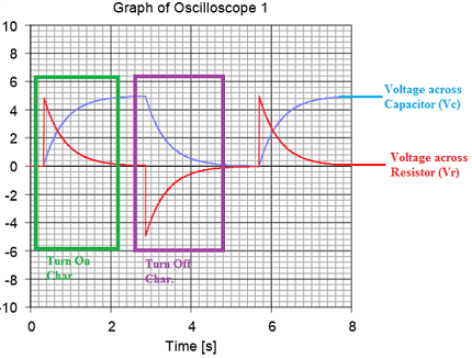
The RC circuit is commonly used as a low-pass filter, allowing low-frequency signals to pass through while blocking high-frequency signals. When a voltage step is applied to an RC circuit, the voltage across the capacitor will rise exponentially until it reaches the applied voltage, at which point it will stop changing.
LR Circuit
An LR circuit is composed of a resistor and an inductor in series. The resistor limits the flow of current in the circuit, while the inductor stores energy in a magnetic field. The time constant of an LR circuit is given by the ratio of the inductance and the resistance (τ = L/R).
The LR circuit is commonly used as a high-pass filter, allowing high-frequency signals to pass through while blocking low-frequency signals. When a voltage step is applied to an LR circuit, the voltage across the inductor will rise linearly until it reaches the applied voltage, at which point it will stop changing.
LC Circuit
An LC circuit is composed of an inductor and a capacitor in series. The inductor stores energy in a magnetic field, while the capacitor stores energy in an electric field. The resonant frequency of an LC circuit is given by the inverse of the product of the square root of the inductance and the capacitance (f = 1/(2π√(LC)).
The LC circuit is commonly used as a resonant circuit, allowing a specific frequency to pass through while blocking other frequencies. At the resonant frequency, the voltage across the inductor and the capacitor are equal and opposite, resulting in a purely resistive load.
LCR Circuit
An LCR circuit is composed of a resistor, an inductor, and a capacitor in series. The resistor limits the flow of current in the circuit, while the inductor and capacitor store energy in a magnetic and electric field, respectively. The behavior of an LCR circuit depends on the frequency of the AC voltage source and the values of the components.
At resonance, the impedance of an LCR circuit is purely resistive, and the circuit behaves as a pure resistive load. The resonant frequency can be calculated using the formula f_resonance = 1/(2π√(LC)). At other frequencies, the impedance of the circuit can be purely capacitive or purely inductive, resulting in a circuit that is not purely resistive.
Conclusion
In conclusion, the RC, LR, LC, and LCR circuits are all important components in electrical engineering. Each circuit has its own unique characteristics and functions, allowing it to be used in a variety of applications. Understanding the basic structure and function of these circuits is essential for any electrical engineer, and can help to improve the performance of circuits in many applications.