
Self-inductance and mutual inductance are two important concepts in the field of electromagnetism.
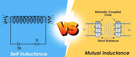
Self-inductance refers to the property of a circuit element, such as a coil or solenoid, to generate an electromotive force (EMF) in itself when the current through it changes. The EMF produced is proportional to the rate of change of the current and the inductance of the element. This effect is due to the production of a magnetic field around the element that opposes the change in the current.
Mutual inductance, on the other hand, refers to the property of two circuit elements to induce EMF in each other when there is a change in the current through one of them. This effect is due to the magnetic field produced by one element that links with the other element, inducing an EMF in it. The magnitude of the induced EMF is proportional to the rate of change of the current in the first element and the mutual inductance between the two elements.
The unit of inductance is the henry (H). Self-inductance is measured in henries, and mutual inductance is measured in henries per meter (H/m) or henries per turn (H/turn).
In practical applications, inductors are widely used in circuits, such as power supplies, filters, and oscillators, where they provide energy storage and filtering. Mutual inductance is used in transformers to step up or step down voltage levels in AC circuits.
What is Required Self and Mutual Inductance
Required self and mutual inductance refer to the values of inductance that are necessary to achieve a specific function or performance in an electrical circuit.
For example, in a power supply circuit, a specific value of self-inductance may be required to filter out unwanted AC noise and ripple from the DC output. In this case, the required self-inductance will depend on the frequency of the AC noise and the desired level of filtering.
In the case of mutual inductance, a specific value may be required in a transformer to step up or step down the voltage of an AC power source. The required mutual inductance will depend on the ratio of the input and output voltages and the number of turns in the primary and secondary windings of the transformer.
To determine the required self or mutual inductance, circuit designers can use mathematical formulas and simulations to calculate the necessary values based on the circuit requirements and specifications. In practical applications, inductors can be selected or designed to meet the required inductance values.
When is Required Self and Mutual Inductance
Required self and mutual inductance are used in various applications where specific circuit performance or functions are required. Here are some examples:
- Power supply filtering: In power supply circuits, inductors are often used for filtering out AC noise and ripple from the DC output. The required self-inductance depends on the frequency of the AC noise and the desired level of filtering.
- Resonant circuits: In resonant circuits, such as those used in radio frequency (RF) applications, the inductance of a coil and a capacitor are carefully chosen to create a specific resonant frequency. The required self-inductance of the coil depends on the capacitance of the capacitor and the desired resonant frequency.
- Transformers: In transformers, mutual inductance is required to step up or step down the voltage of an AC power source. The required mutual inductance depends on the ratio of the input and output voltages and the number of turns in the primary and secondary windings of the transformer.
- Induction motors: In induction motors, the rotor is induced with a magnetic field produced by the stator winding. The required mutual inductance between the rotor and stator depends on the design of the motor and the desired level of torque.
To determine the required self or mutual inductance in these applications, circuit designers use mathematical formulas and simulations to calculate the necessary values based on the circuit requirements and specifications. The inductors can then be selected or designed to meet the required inductance values.
Where is Required Self and Mutual Inductance
Required self and mutual inductance can be found in various electrical and electronic circuits. Here are some examples:
- Power supplies: Self-inductors are often used in power supply circuits to filter out AC noise and ripple from the DC output.
- Resonant circuits: Resonant circuits, such as those used in radio frequency (RF) applications, require careful selection of inductors and capacitors to create a specific resonant frequency.
- Transformers: Transformers use mutual inductance to step up or step down the voltage of an AC power source.
- Induction motors: Induction motors use mutual inductance between the rotor and stator to produce torque.
- Electronic filters: Inductors are used in electronic filters, such as high-pass and low-pass filters, to pass or reject certain frequencies.
- Oscillators: Inductors are used in oscillator circuits to create a resonant frequency.
- Chokes: Inductors are used as chokes in circuits to limit the flow of AC current.
These are just a few examples of where required self and mutual inductance can be found. In general, inductors are widely used in electrical and electronic circuits where energy storage, filtering, or signal processing is required.
How is Required Self and Mutual Inductance
The required self and mutual inductance can be calculated using mathematical formulas and simulations based on the requirements of a specific circuit or application. The following are some examples of how the required self and mutual inductance can be calculated:
- Power supply filtering: The required self-inductance of an inductor used in power supply filtering can be calculated using the following formula:L = Vripple * Toff / (ΔIL * f)Where L is the required self-inductance, Vripple is the allowable AC ripple voltage, Toff is the off-time of the switching regulator, ΔIL is the change in inductor current, and f is the switching frequency.
- Resonant circuits: The required self-inductance of a coil in a resonant circuit can be calculated using the following formula:L = 1 / (4π^2 f^2 C)Where L is the required self-inductance, f is the resonant frequency, and C is the capacitance of the capacitor.
- Transformers: The required mutual inductance in a transformer can be calculated using the following formula:M = Vout / (Vin * √(1 – D))Where M is the required mutual inductance, Vin is the input voltage, Vout is the output voltage, and D is the duty cycle of the transformer.
- Induction motors: The required mutual inductance in an induction motor depends on the design of the motor and the desired level of torque. Simulation software can be used to calculate the required mutual inductance based on the motor design and performance requirements.
In general, the required self and mutual inductance can be determined by analyzing the circuit requirements and using mathematical formulas and simulations to calculate the necessary values. Once the required inductance is determined, inductors can be selected or designed to meet the required specifications.
Nomenclature of Self and Mutual Inductance
Self-inductance is a property of a circuit element, such as a coil, that describes the amount of magnetic flux generated by a current flowing through the element. It is measured in units of henries (H) and is denoted by the symbol L. The self-inductance of a coil is determined by the number of turns in the coil, the cross-sectional area of the coil, and the material properties of the core.
Mutual inductance is a property of two circuit elements, such as two coils, that describes the amount of magnetic flux generated in one element by a current flowing in the other. It is also measured in units of henries and is denoted by the symbol M. The mutual inductance between two coils depends on the geometry of the coils, the number of turns in each coil, and the distance between the coils.
The relationship between the self-inductance of a coil and the mutual inductance between two coils can be expressed using the following equations:
- The self-inductance of a coil with N turns and magnetic flux Φ is L = Φ/I, where I is the current flowing through the coil.
- The mutual inductance between two coils with N1 and N2 turns, carrying currents I1 and I2, respectively, and separated by a distance d, is M = Φ21/I1, where Φ21 is the magnetic flux generated in coil 2 by the current flowing in coil 1.
These equations show that self-inductance and mutual inductance are related to the magnetic flux generated by a current flowing through a coil, and that mutual inductance depends on the geometry and relative position of two coils.
Case Study on Self and Mutual Inductance
One practical application of self and mutual inductance is in the design and operation of transformers. Transformers are electrical devices that use the principles of electromagnetic induction to transfer electrical energy from one circuit to another. They are commonly used in power distribution systems to step up or step down the voltage of alternating current (AC) power.
In a transformer, there are two coils, a primary coil and a secondary coil, that are wound around a common magnetic core. The primary coil is connected to a source of AC power, and the secondary coil is connected to a load. When AC power is applied to the primary coil, it generates a time-varying magnetic field that induces a voltage in the secondary coil, which in turn drives a current in the load.
The amount of voltage induced in the secondary coil depends on the ratio of the number of turns in the primary and secondary coils, as well as the magnetic properties of the core material. This ratio is called the turns ratio, and is denoted by Np/Ns, where Np is the number of turns in the primary coil and Ns is the number of turns in the secondary coil.
The voltage induced in the secondary coil can also be affected by the magnetic flux generated by the primary coil, which is a function of the current flowing through the primary coil and the self-inductance of the primary coil. The self-inductance of the primary coil can be calculated using the equation Lp = Φp/Ip, where Φp is the magnetic flux generated by the current flowing through the primary coil and Ip is the current flowing through the primary coil.
The mutual inductance between the primary and secondary coils can also affect the voltage induced in the secondary coil. The mutual inductance can be calculated using the equation M = Φs/Ip, where Φs is the magnetic flux generated by the current flowing through the primary coil that is linked to the secondary coil, and Ip is the current flowing through the primary coil.
In summary, the self and mutual inductance of the coils in a transformer play a crucial role in determining the voltage induced in the secondary coil, and ultimately, the efficiency and performance of the transformer. By carefully selecting the number of turns in the coils and the magnetic properties of the core material, engineers can design transformers that are optimized for specific applications, such as power distribution or electric motors.
White paper on Self and Mutual Inductance
Introduction
Self and mutual inductance are fundamental concepts in the study of electromagnetism and play important roles in the design and operation of electrical devices such as transformers and motors. In this white paper, we will explore the principles of self and mutual inductance, their mathematical equations, and practical applications.
Self-Inductance
Self-inductance is a property of a circuit element, such as a coil, that describes the amount of magnetic flux generated by a current flowing through the element. The self-inductance of a coil is measured in units of henries (H) and is denoted by the symbol L. The self-inductance of a coil is determined by the number of turns in the coil, the cross-sectional area of the coil, and the material properties of the core. The self-inductance of a coil is proportional to the square of the number of turns in the coil and is directly proportional to the cross-sectional area of the coil.
The relationship between the self-inductance of a coil and the magnetic flux generated by a current flowing through the coil is described by the equation L = Φ/I, where Φ is the magnetic flux generated by the current flowing through the coil, and I is the current flowing through the coil. This equation shows that the self-inductance of a coil depends on the amount of magnetic flux generated by the current flowing through the coil and is independent of the properties of other coils in the circuit.
Mutual Inductance
Mutual inductance is a property of two circuit elements, such as two coils, that describes the amount of magnetic flux generated in one element by a current flowing in the other. The mutual inductance between two coils is measured in units of henries and is denoted by the symbol M. The mutual inductance between two coils depends on the geometry of the coils, the number of turns in each coil, and the distance between the coils.
The relationship between the mutual inductance between two coils and the magnetic flux generated in one coil by a current flowing in the other is described by the equation M = Φ21/I1, where Φ21 is the magnetic flux generated in coil 2 by the current flowing in coil 1, and I1 is the current flowing through coil 1. This equation shows that the mutual inductance between two coils depends on the amount of magnetic flux generated in one coil by the current flowing in the other and is independent of the properties of other coils in the circuit.
Practical Applications
Self and mutual inductance have many practical applications in the design and operation of electrical devices. One important application is in the design of transformers. Transformers are electrical devices that use the principles of electromagnetic induction to transfer electrical energy from one circuit to another. The self and mutual inductance of the coils in a transformer play a crucial role in determining the voltage induced in the secondary coil, and ultimately, the efficiency and performance of the transformer. By carefully selecting the number of turns in the coils and the magnetic properties of the core material, engineers can design transformers that are optimized for specific applications, such as power distribution or electric motors.
Another important application of self and mutual inductance is in the design of electric motors. Electric motors use the principles of electromagnetic induction to convert electrical energy into mechanical energy. The self and mutual inductance of the coils in an electric motor play a crucial role in determining the torque and speed of the motor. By carefully selecting the number of turns in the coils and the magnetic properties of the core material, engineers can design electric motors that are optimized for specific applications, such as industrial machinery or automotive systems.
Conclusion
Self and mutual inductance are key principles in the field of electromagnetism that have numerous practical applications in the design and operation of electrical devices. Understanding these principles is crucial for engineers and scientists working in fields such as power systems, electric motors, and telecommunications. By carefully designing circuits and devices that take advantage of self and mutual inductance, engineers can create efficient and high-performing systems that meet the needs of a wide range of applications. As technology continues to advance, the importance of self and mutual inductance will only continue to grow, making it an essential concept to study for anyone interested in the field of electrical engineering.